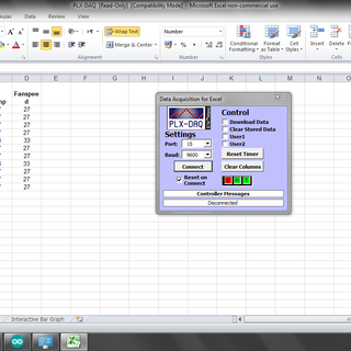
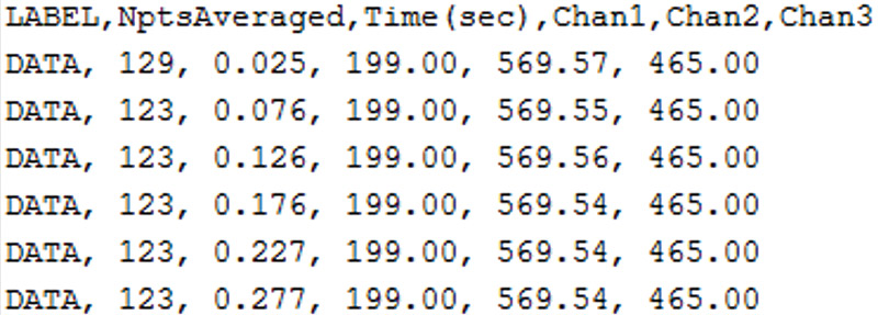
If you have Office 2003 or older you can send data to Excel directly by using the PLX macro, which effectively makes Excel into a terminal. If you don't, getting a copy is a really good idea. If you can't, you can send the data to a proper terminal programme, like RealTerm, instead. This can record your data to CSV file and even include a.
- Arduino Data Acquisition Into Excel Download
- Arduino-based Data Acquisition Into Excel Labview And Matlab
- Arduino Data Acquisition Into Excel Tutorial
So I made a system using Arduino and the amazing 1sheeld to save LDR readings in an Excel sheet and that is what we are going to do now. LDR is an acronym for 'light dependent resistor' as it's a resistance but its value changed with light in the environment. 1Sheeld is a platform for Arduino that allows you to tap into your smartphone's. We know that Arduino allows to acquire data in the analog input. We can use Excel to store data in a sheet and display it in a graph using an application available on the network called PLX-DAQ (Parallax Data Acquisition), but this software doesn't work under Windows 10 and is no longer supported. The Simplest Way to Get Data from an Arduino into Microsoft Excel PLX-DAQ is really a macro that runs in Microsoft Excel. It is free and can be downloaded from Parallax, Inc. Ironically, it was originally written for Stamp microcontrollers — a competitor to Arduinos; My main concern is data acquisition from arduino + shield into matlab.
Few weeks ago I made a datalogger using Arduino, SD card, DS3231 real time clock chip and DHT22 sensor which logs: date, time, temperature and humidity values where data is stored on a text file in the SD card.
This topic shows how to build the same data logger using Arduino, DHT22 sensor and Microsoft Excel where the Arduino sends data (temperature and humidity) serially to an Excel sheet.
Related Projects:
Arduino datalogger with SD card, DS3231 and DHT22 sensor
Arduino with DHT22 sensor and LCD
Hardware Required:
- Arduino board
- DHT22 digital humidity and temperature sensor
- 4.7k ohm resistor
- Breadboard
- Jumper wires
Arduino Data Acquisition Into Excel Download
The Circuit:
Project circuit schematic is shown below.

As shown above, the circuit is very simple we need the DHT22 sensor only and there is no need for a real time clock chip (DS3231, DS1302, DS1307 …) because Microsoft Excel can get data and time information from Windows.
The DHT22 sensor has 4 pins (from left to right): VCC (5V), data, NC (not connected pin) and GND. Data pin is connected to Arduino UNO pin 2.
Arduino Code:
To read data (temperature and humidity) from the DHT22 sensor we need a small library which can be downloaded from the link below. After downloading the library, it can be added to Arduino IDE by going to: Sketch –> Include Library –> Add .ZIP Library …
Adafruit DHT sensor library – GitHub
In order to send data serially from the Arduino board to Excel we need a small software named PLX-DAQ (Parallax Data Acquisition tool). This software is just an add-in for Microsoft Excel. PLX-DAQ download link can be found in the page below:
https://www.parallax.com/downloads/plx-daq
After downloading and installing you will see a new folder created in your PC desktop named: PLX-DAQ which contains two shortcut files: PLX-DAQ Help File and PLX-DAQ Spreadsheet. Double click (or open using Excel) on the second file (PLX-DAQ Spreadsheet) gives a window as the one shown in the picture below. If there is a security warning (macros have been disabled) just click on Options –> check: Enable this content –> OK . Note that this plugin was tested with Microsoft Office 2007 and it should work with Office 2010, but unfortunately it doesn’t work with Office 2013.
To start receiving data just choose the COM port and baud rate then click on Connect (Arduino IDE serial monitor must be closed before connecting with PLX-DAQ software).
Full Arduino code:
Finally as a result I got the following Excel sheet:
If you have a problem with time column (column B) just select that column –> right mouse click –> Format Cells (a new window will open) –> select Time (from a list on the left) –> OK .

We know that Arduino allows to acquire data in the analog input. We can use Excel to store data in a sheet and display it in a graph using an application available on the network called PLX-DAQ (Parallax Data Acquisition), but this software doesn't work under Windows 10 and is no longer supported. So we can found a new version of PLX-DAQ re-written by NetDevil, an Arduino forum's member, to be able to be run on modern systems.

We want to measure the voltage variations from a trimmer. We take a device of any ohmic value and connect its two external pins respectively to 5V and GND pins supplied by Arduino. We pick up the voltage signal offered by the central pin, which varies according to the resistive divider that is formed while we turn its knob.
To collect data from our experiment, we can open the PLX-DAQ-v2.11.xlsm worksheet which contains a macro that allows us to save the data from the USB in Excel. To do this, we need to open PLX DAQ clicking on the respectively button and in the popup that the software opens we choose the USB Port to which Arduino is connected. Before clicking on the Connect button, we have to open Arduino IDE and use the sketch that is reported below, or use that is provided with PLX-DAQ software distribution.
#define sensorPin A0 // select the input pin for the potentiometerint sensorValue = 0; // variable to store the value coming from the sensor 0-1023float sensorVoltage = 0; // variable to store the voltage coming from the sensor 0-5V
void setup() { Serial.begin(9600); Serial.println('CLEARDATA'); Serial.println('LABEL,t,A0');}
void loop() { // read the value from the sensor sensorValue = analogRead(sensorPin); // calculate voltage sensorVoltage = sensorValue*5.0/1023.0; // send value to USB Serial.print('DATA,TIME,'); Serial.println(sensorVoltage); // delay 100ms delay(100);}
Arduino-based Data Acquisition Into Excel Labview And Matlab
Let's load this sketch in Arduino, which will send data read from the analog port A0 on the USB, associating them with the instant of acquisition time. We have programmed the Serial.print instructions according to the modality proposed by PLX-DAQ (see the reactive help for more details).
Arduino transforms all the signals that it receives on analogue pins into levels between 0 and 1023, so it is our task to enter in the sketch the calculations necessary to return the correct interpretation to the numerical values obtained. In this case the range 0÷1023 represents the voltages between 0÷5V, so we insert the instruction: sensorVoltage = sensorValue*5.0/1023.0
Arduino Data Acquisition Into Excel Tutorial
Before activating PLX-DAQ, we select column B and we assign a 2-Dline type graph to it. In this way, in addition to the data collection, we can see the temporary trend of the signal on the graph.
All versions of PLX-DAQ work good with Excel 2016.


